
A physical design engineer’s main focus is to achieve a decent Quality of Result (QoR) and optimized Power Performance and Area (PPA). The start of this journey begins with the Floorplan steps. What will you achieve at the end of PnR is depends on how good your floorplan is. In case of a macro dominating block, the importance of quality floorplan is quite more. To achieve a good floorplan in a macro dominating block, it might take several iterations and also requires good experience. A detailed analysis of data flow, hierarchy, macro to input-output pins connection, logical depth and many more factors which need to understand and analyzed thoroughly to produce a good floorplan. In this article, we will discuss some of the basic rules on which are helpful to produce a good floorplan and so good QoR.
There are some basic rules of macro placement which help to produce a good floorplan. There are many things which can be analyzed only after the first cut of floorplan result and macro placement can be improved in a few iterations in macro dominating blocks. There are some standard rules which help to achieve a good floorplan.
Grouping of macros as per hierarchy
Analysis of macro to input/output pins connection
Logical depth analysis among macros and macros to Input/Output pin
Maximizing the core area
Avoid notch formation
Channel spacing
Macro abbutment
IO pins to macro spacing
Halo over macros
Routing blockage over macros
Partial placement blockage in the macro channels and macro to io pins region
Above rules are the standard floorplan rules which generally people use as a thumb rule for better and timing and congestion results. Here it is important to understand that a where a well-planed floorplan can result in god timing and congestion result at the same time if the floorplan is not well planned could result in high congestion and high WNS/TNS/FEPs (Worst Negative Slack / Total Negative Slack / Failing End Points). So It is very important to follow the standard practice of macro placement to avoid high congestion and bad timings.
Grouping of macros as per hierarchy
In a hierarchical design, macros must be placed as per their group in the hierarchy. We can highlight the macros with different clours as per their group for better visibility of macro groups. PnR tools provide the option to see the macros and standard cells as per their hierarchy. For Innovus GUI this can be explored as Design Browser –> Modules
 |
| Macro Grouping |
 |
| Design Browser in Innovus |
Analysis of macro to Input/Output pin connections
Generally, we place the macros near to their io pins and if the logic level is only one than we can not put macro away from the pins to avoid in2reg or reg2out timing violation. So we need to check fanin and fanout of macro and try to place them near the connected pins.
Logical depth analysis among macros and macros to Input/Output pins
Inside the groups of macro, the macro order must be as per their logical connection. Macro directly talking to each other should be placed together. Similarly, if two groups of macros have a logical connection with one register (only one level) we can not place them far away. But yes if two groups of a macro taking each other with logic level 3 or 4 or more, we can place them relatively apart from each other.
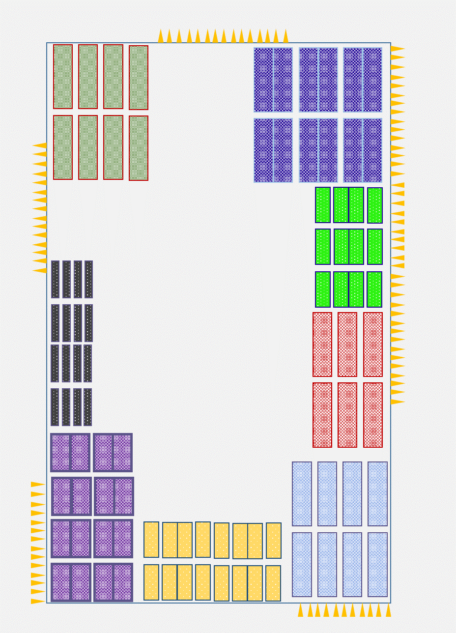
Maximize the core area
We always try to maximize the core area so that standard cells get more room for placement. If there are more rooms for placement there will be less chance of congestion and ultimately shorts. Generally, we try to place all the macro near the core boundary and try to maximize the centre area for the standard cells.
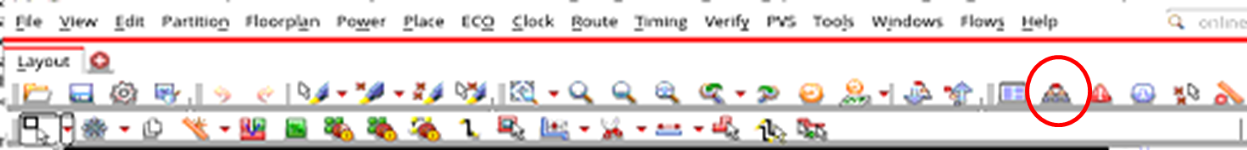
Avoid notch formation
Notch area is not utilised effectively, so it will increase the placement density of the core and will rise the congestion. We always keep in mind while macro placement that notch should not be formed while macro placement especially in the case where the macro count is high and the placement density is also high.
A notch formation is shown in the figure below by the red circled area. This can be avoided in the macro placement style used in first figure.
 |
| Notch formation in macro placement |
Macro channel spacing
The area between two close macros is termed macro channel spacing. In the macro channel, there will be standard cell placement and need a power connection. But if the macro spacing is too less, there is a chance that the power rails in not connected to power straps which is problematic.
 |
| Macro channel spacing |
If there is area crunch we can abut two macros as shown on the right side of the image. But if we are not abutting the macro than between two macros the spacing should be minimum in which at least one VDD and VSS stripe should cross. If the channel width is too low so that no power strip crosses in this area then the rails of this region will not get power. The channel on the left side of the above figure is problematic as the standard cells seating in this region may lose PG connection.
Macro abutment
If required we can abut two macros as shown on the right side of the above figure. Only thing two remember while abutment is this pins should not be on the abutment edge. Pins should be on non-abbutment edge.
IO pins to macro spacing
If there are no pins on the core boundary we can place the macro close to the boundary but on the boundary, there are io pins, we should place macro a with some spacing to avoid congestion near the pins.
Halo over the macro
Halo is nothing but a placement blockage which are associated with macro, so if we move macro, the halo will move accordingly. To avoid the congestion on the edge of macro and also base DRC we avoid placing standard cells on the edge of the macro. A halo is put on the macro to block around the macro.
Routing blockage over the macro
Macro designing needs some more metal layers as compared to standard cells. So the metal layers already used inside the macro can not be used for routing over macro and need to block over the macro. So we need routing blockage over the macro.
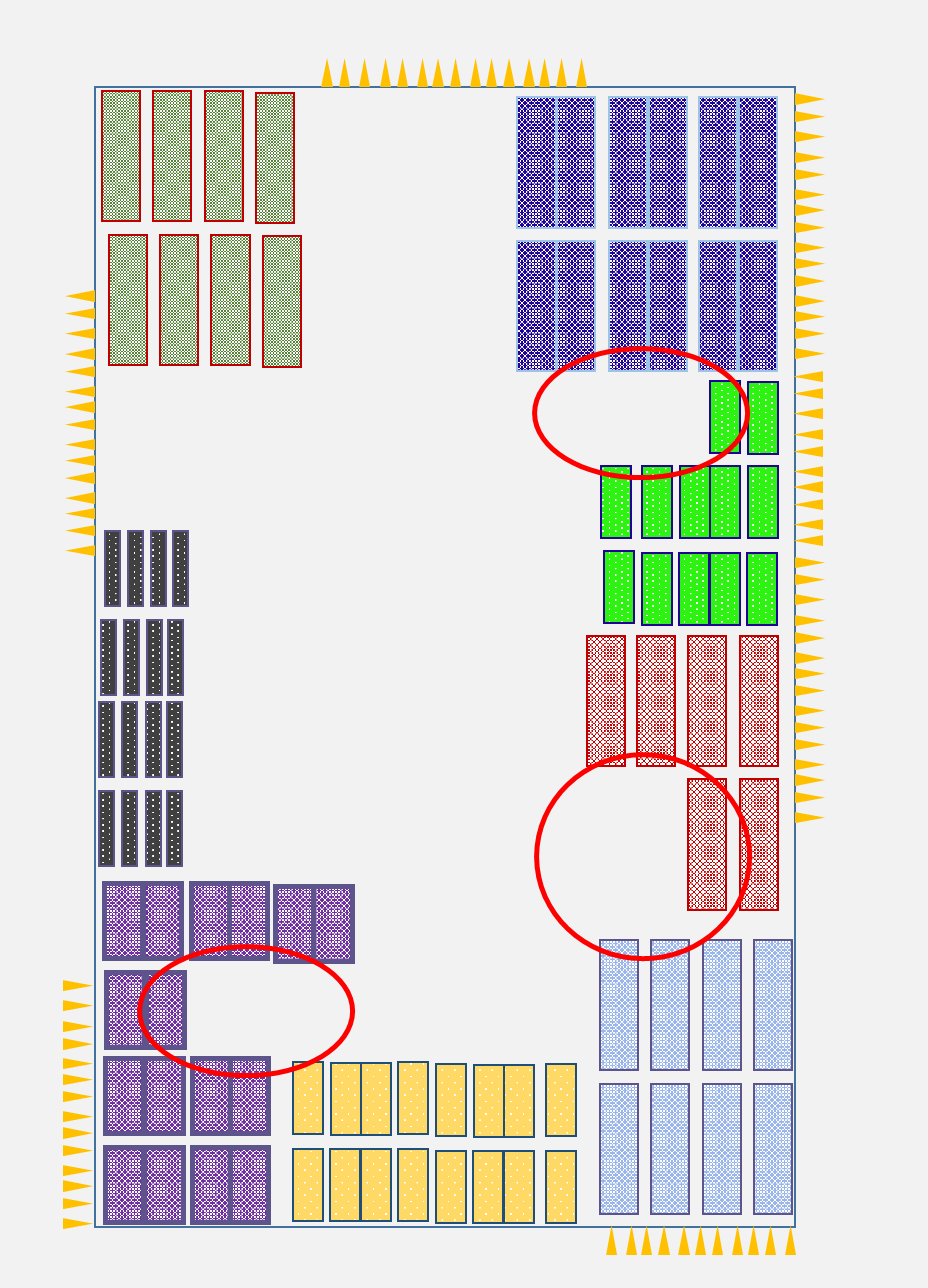
Partial placement blockage in macro channel and macro to io pins area
To avoid congestion in the macro channels, We apply partial placement blockage in the macro channel so that we can control the placement density. We can also apply the partial placement blockage in the region between io pins and macro as shown in the figure below. All yellow region is showing the partial placement blockage region, we can set the placement density in these regions.
 |
| Partial placement blockage |
Macro placement is the most important part of PnR as the QoR strongly depends on the macro placement. The above-mentioned rules are standard rules which generally followed in macro dominating blocks.
Well explained 👍
sir i am preparing for interview and i encountered a question somewhere the other day. pls care to explain as soon as possible. what was spacing between macros with channel and without channel (in 7nm)? i was thinking how is this possible to have spacing without channel?
Hi
its based on user defined grid, but sorry, exact number can't be posted here.
Yes it is possible.